Specialised CAD Toolsets for Faster, More Accurate Design
AutoCAD includes a range of industry-specific toolsets developed to improve efficiency, reduce repetitive drafting, and support discipline-based workflows.
By using these integrated toolsets, professionals in South Africa can achieve up to 63% higher productivity compared to standard AutoCAD, depending on the task and industry.
Architecture Toolset
Architectural Design and Documentation Tools
The AutoCAD Architecture toolset supports building design workflows with intelligent objects and automation features aligned to real-world construction.
Users can experience up to 61% improved productivity when working on architectural drafting and documentation.
What’s New in AutoCAD Architecture 2027
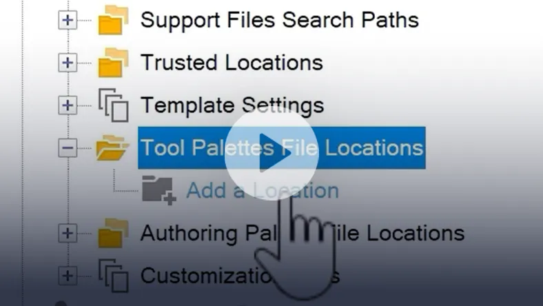
Connected Support Files
Improved integration with cloud-based file management allows CAD managers to centrally control support files. This ensures correct templates, palettes, and configurations are applied automatically.
Structural Member Coordinates
Export start and end coordinates of structural members directly to Excel for easier reporting and collaboration.
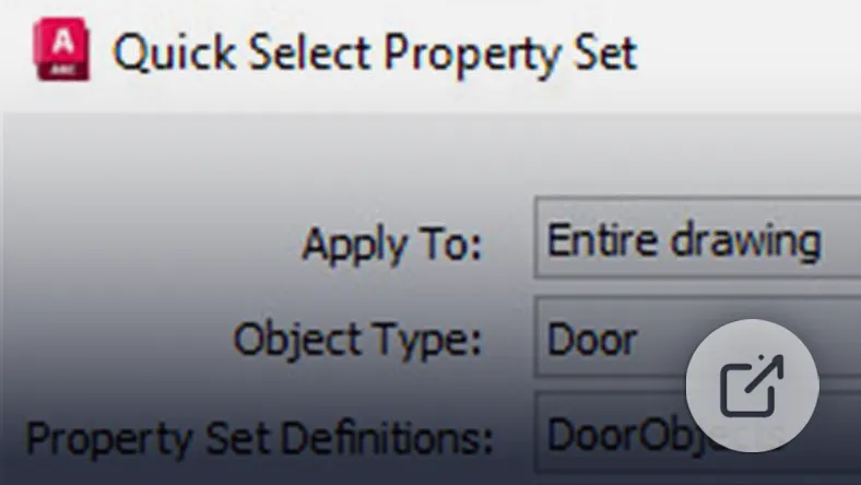
Quick Select Property Set
Filter and select objects based on type and shared property values within a drawing.
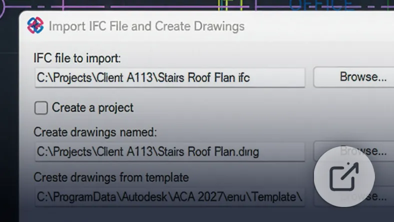
IFC Enhancements
Improved performance and reliability when working with IFC files across Architecture and MEP workflows.
Activity Insights
Track renovation-related actions and access detailed activity data for better project oversight.
Navigation Improvements
Expanded project navigation controls allow faster access to drawing structures.
Core Architecture Features
Access 8,800+ architectural components, including walls, doors, and windows
Automatically generate floor plans, elevations, sections, and ceiling grids
Work with objects that reflect real-world construction behaviour
Manage drawing versions with check-in/check-out functionality
Apply and customise layer standards automatically
Use a display system that adapts objects across different views
Organise layouts using spaces and zones
Access detailed component libraries for construction detailing
Manage renovation projects within a single drawing
Benefits
Reduce repetitive drafting tasks
Improve drawing accuracy and consistency
Support collaboration across architectural teams
Deliver projects faster with fewer errors
Mechanical Toolset
Mechanical Engineering Design Tools
The AutoCAD Mechanical toolset is built for mechanical engineers and designers, helping automate common tasks and standardise workflows.
This toolset can deliver up to 55% productivity improvements for mechanical design work.
What’s New in AutoCAD Mechanical 2027
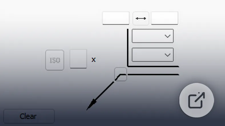
Updated ISO Standards
Support for the latest ISO13715:2017 edge symbol revisions.
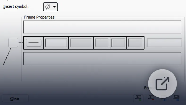
ASME Standard Updates
Includes updated Feature Control Frame and datum symbols based on ASME Y14.5M-2018 (R2024).
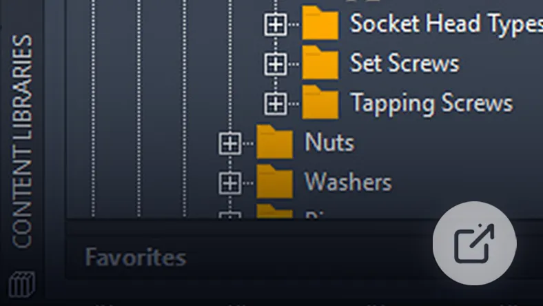
Enhanced Content Library
Over 800 standard parts updated to the latest revisions.
Connected Support Files
Centralised control of support files improves consistency across teams.
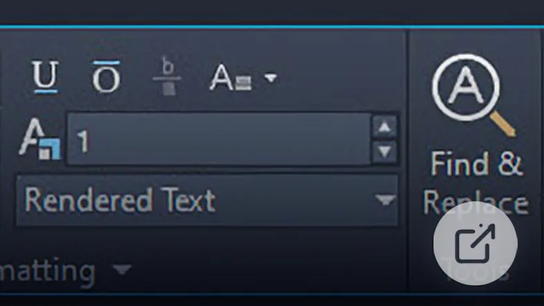
Find and Replace Enhancements
Expanded search functionality within leader notes for faster editing.
Core Mechanical Features
Access 700,000+ standard parts and features across global standards
Automate layer creation for mechanical drawings
Generate BOMs, part lists, and annotations automatically
Use pre-configured GD&T symbols and annotations
Customise borders and title blocks
Improve detailing with specialised drafting tools
Perform 2D calculations such as FEA and shaft analysis
The AutoCAD Map 3D toolset enables users to integrate CAD and GIS data for infrastructure planning and geospatial analysis.
Users can achieve up to 60% productivity gains when working with mapping and spatial data.
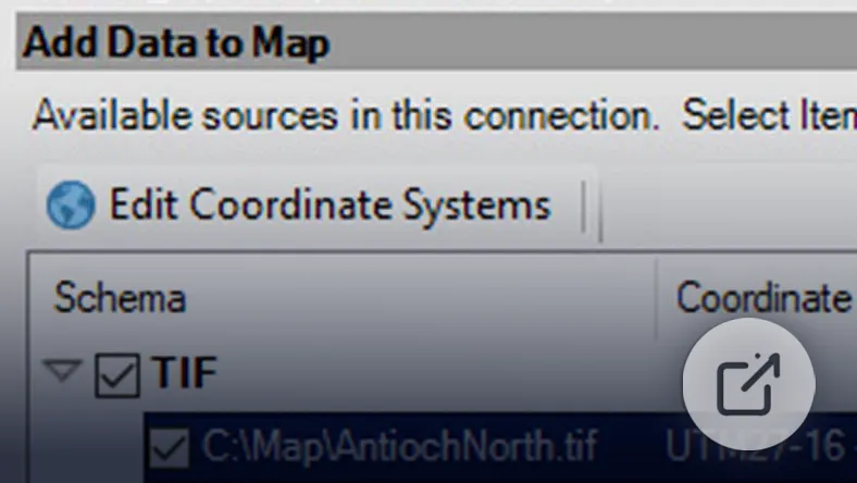
What’s New in AutoCAD Map 3D 2027
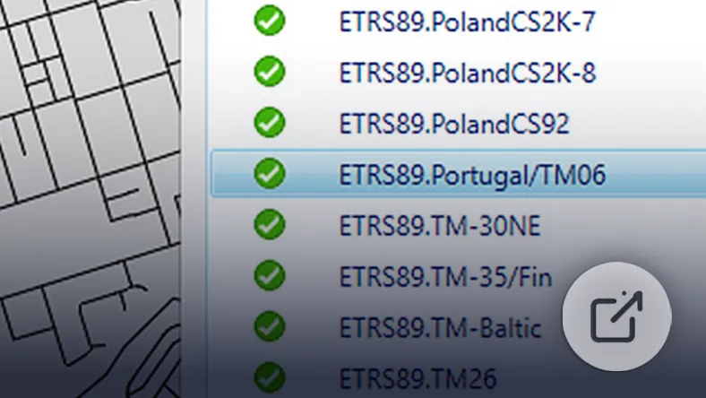
Coordinate System Updates
Improved accuracy for geospatial transformations.
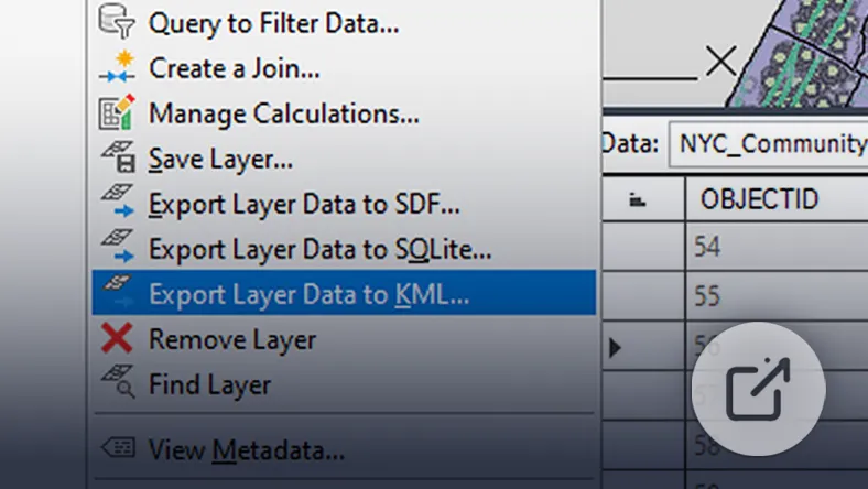
Export to KML
Export GIS data for use in mapping and visualisation platforms.
ArcGIS Integration
Access and work with enterprise GIS databases directly.
Vertical Coordinate System Support
Expanded coordinate system capabilities for more accurate modelling.
Connected Support Files
Centralised management of project resources.
Core Map 3D Features
Work with multiple CAD and GIS data formats
Connect directly to ArcGIS and enterprise databases
Convert data between DWG and GIS formatsrt lists, and annotations automatically
Edit geospatial data using standard AutoCAD tools
Perform drawing cleanup to fix errors
Analyse spatial data using buffers and overlays
Create thematic maps and visualisations
Benefits
Improve infrastructure planning accuracy
Reduce data conversion errors
Enhance GIS and CAD collaboration
Support large-scale mapping projects
MEP Toolset
Mechanical, Electrical and Plumbing Design
The AutoCAD MEP toolset provides specialised tools for building services design, helping teams work more efficiently with intelligent objects.
This toolset offers up to 85% productivity improvements.
What’s New in AutoCAD MEP 2027
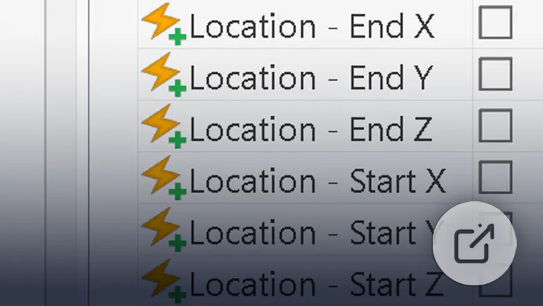
Structural Member Export
Export structural member coordinates directly to Excel for easier documentation and collaboration.
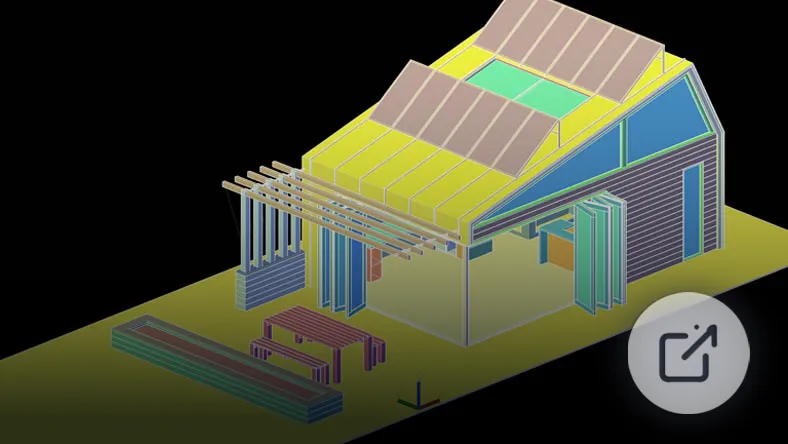
Improved Graphics Performance
Experience smoother navigation and improved responsiveness when working on complex building systems.
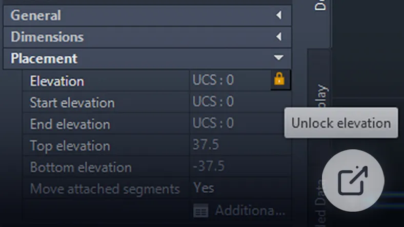
Elevation Locking
Lock object elevations to help maintain design accuracy and reduce placement errors.
Enhanced IFC Support
Improved IFC compatibility enables better coordination and data exchange across BIM workflows.
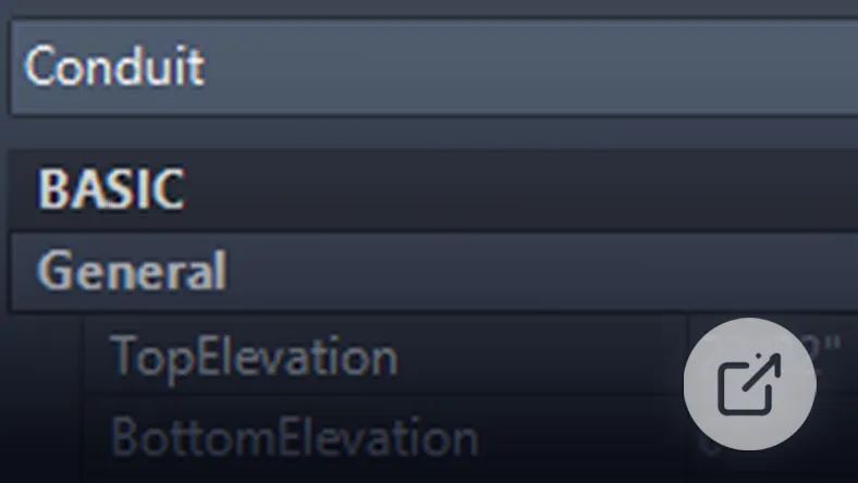
Improved Conduit Alignment
Updated conduit alignment tools help create cleaner and more consistent electrical layouts.
Connected Support Files
Centralised management of support files helps maintain standards across teams and projects.
Core MEP Features
Access 10,500+ intelligent MEP objects
Use discipline-specific workspaces
Automatically update drawings and schedules
Manage drawing versions and revisions
Organise layouts using spaces and zones
Apply and customise layer standards
Benefits
Reduce coordination errors between systems
Improve accuracy of building services design
Speed up documentation processes
Support multi-discipline collaboration
Electrical Toolset
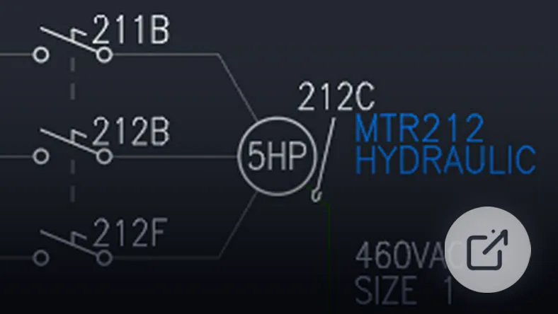
Electrical Design and Automation
The AutoCAD Electrical toolset is designed for electrical engineers, offering automation and comprehensive symbol libraries.
It can deliver up to 95% productivity improvements.
What’s New in AutoCAD Electrical 2027
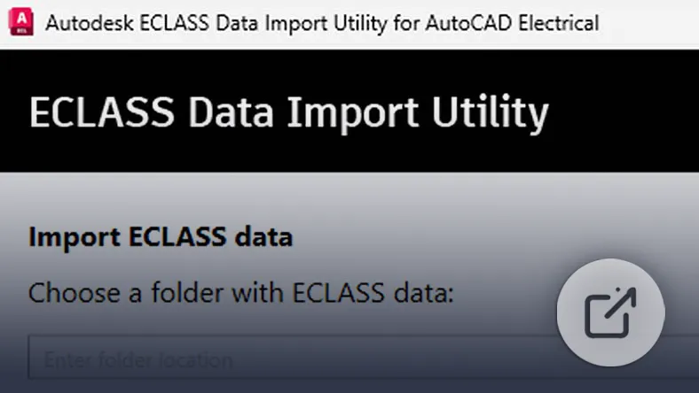
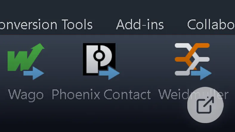
ECLASS Data Import
Import ECLASS manufacturer data to improve component consistency and standardisation.
Terminal Strip Export
Export terminal strip data to external systems for streamlined manufacturing and documentation workflows.
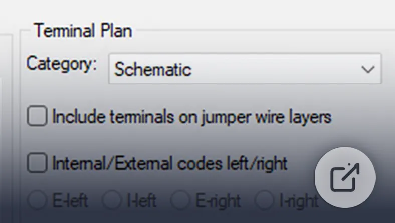
Improved Terminal Reporting
Generate clearer and more detailed terminal reports for improved project management.
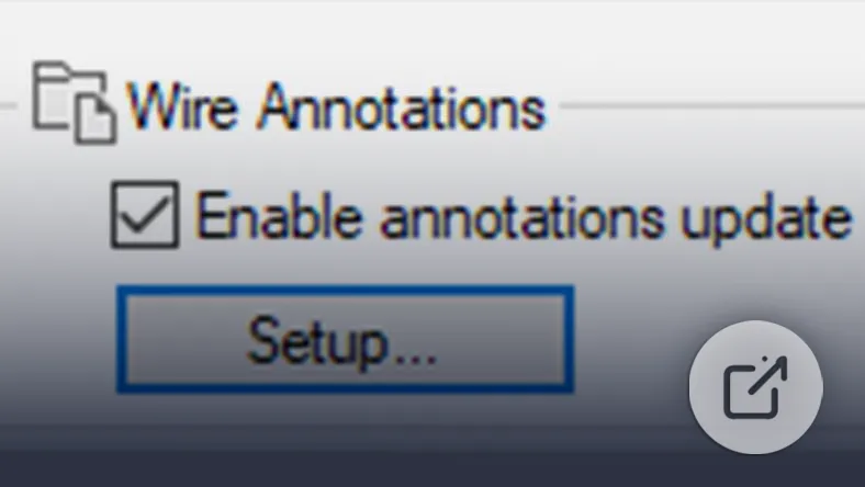
Enhanced Wire Numbering
Updated wire numbering tools help maintain accurate and organised electrical schematics.
Expanded Cable Marker Library
Access a broader range of cable markers to support more standardised electrical documentation.
Connected Support Files
Centralised support file management helps teams maintain consistency across projects.
Core Electrical Features
Access 65,000+ electrical symbols
Automate wire numbering and component tagging
Generate reports automatically
Support current and legacy electrical standards
Manage projects with built-in tools
Reuse circuit designs with Circuit Builder
Generate PLC drawings from spreadsheets
Benefits
Reduce manual electrical drafting
Improve design accuracy
Standardise electrical documentation
Speed up panel and circuit design
Plant 3D Toolset
Process Plant Design and Modelling
The AutoCAD Plant 3D toolset supports plant design workflows, including P&IDs and 3D modelling.
Users can achieve up to 74% productivity gains.
What’s New in AutoCAD Plant 3D 2027
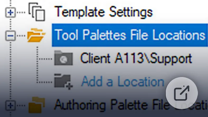
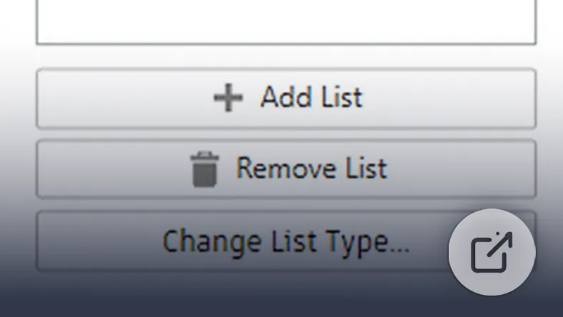
Shared Tool Palettes
Share tool palettes across teams to improve standardisation and workflow consistency.
Improved Selection Lists
Enhanced selection list management makes it easier to organise and work with project components.
Multi-Sheet Isometrics
Create multi-sheet isometric drawings more efficiently for complex piping systems.
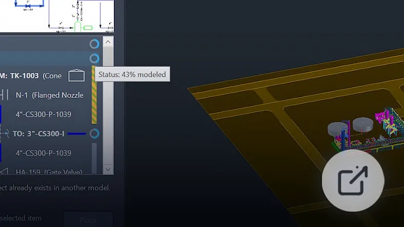
Piping Completion Tracking
Track 3D piping completion progress more effectively throughout project development.
Enhanced P&ID Selection
Improved P&ID selection tools help speed up editing and project navigation tasks.
Improved Collaboration
Updated collaboration workflows support smoother coordination across project teams.
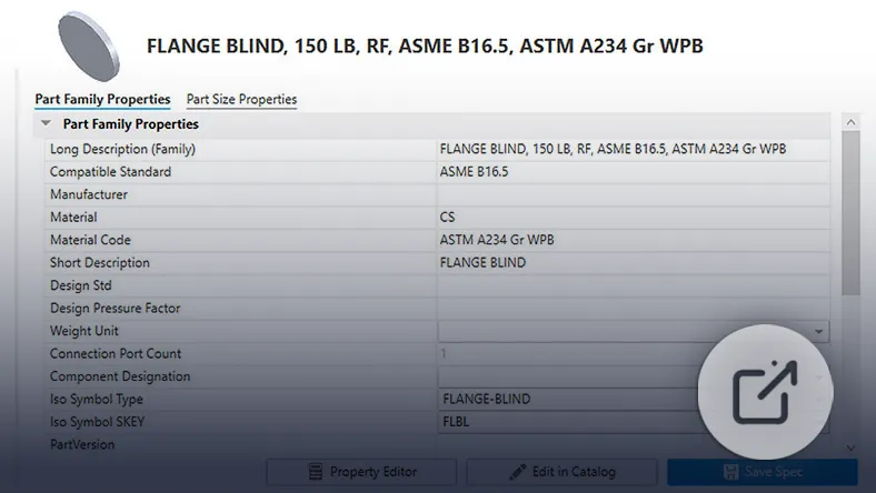
Spec Editor Enhancements
Updates to the Spec Editor and modelling tools improve efficiency and project accuracy.
Connected Support Files
Centralised management of support files helps maintain standards across teams and projects.
Core Plant 3D Features
Collaboration and P&IDs
Work in a shared project environment
Create and edit P&ID drawings efficiently
Use industry-standard symbol libraries
Validate data for consistency
3D Modelling
Create plant models using parametric equipment
Design structures and piping systems
Customise project-specific specifications
Piping Documentation
Generate orthographic drawings from 3D models
Create isometric drawings automatically
Produce project reports directly from models
Benefits
Improve plant design accuracy
Reduce rework and design clashes
Enhance collaboration across teams
Speed up project delivery
Raster Design Toolset
Raster Editing and Conversion Tools
The Raster Design toolset helps users work with scanned drawings and raster images within AutoCAD.
It can improve productivity by up to 48%.
Core Raster Features
Clean and edit raster images
Convert raster files into vector drawings
Edit raster geometry using AutoCAD tools
Analyse and transform geospatial images
Benefits
Reduce time spent recreating drawings
Improve accuracy when working with legacy plans
Convert scanned data into usable CAD files
Productivity Disclaimer
Productivity gains are based on Autodesk-commissioned studies comparing standard AutoCAD workflows with specialised toolsets. Actual results may vary depending on hardware, workflows, and project complexity.
Have Questions About Complex Applications?
Speak to us about your operational requirements or outcomes and
we'll tailor a solution best suited to your business.