
While you can add secondary faces or contour flanges to form a rim on a sheet metal part, the flange command is specifically tailored for this purpose. Creating a flange is simpler than adding a secondary face for two key reasons. First, the flange command creates a flat feature directly, meaning no separate sketch is needed, making it faster to apply. Second, if you want to create a rim at an angle other than 90 degrees, the flange command allows you to do this without needing to set up a new plane. Additionally, the flange command includes options to precisely define the position of the bend, which can sometimes be more challenging to align when using secondary faces.
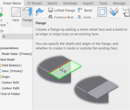
Steps to Create a Flange:
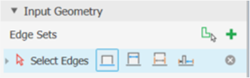
- Begin with your base part. Once the base part is ready, select the edges where you want to add the flange.
- Choose from different options for defining the flange: edge, width, between, or offset.
- Edge: The flange is created along a single edge.
- Width: Sets the flange width uniformly from the edge.
- Between: Defines the flange width between two selected edges.
- Offset: Allows you to set a custom offset distance from the edge.
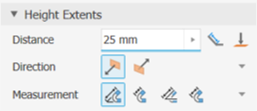
- In the height section, specify the distance the flange will rise.
- Choose the direction—this controls how the flange is oriented.
- Measure from one of several options:
- From the intersection of two outer faces
- From the intersection of two inner faces
- From a selected edge
- From a tangent plane
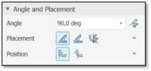
- Set the angle of the flange—define the angle you want.
- Choose the placement:
- Plane through the part edge
- Plane through a selected edge
- Plane tangent to or at a side face
- A sketch plane
- Set the position of the flange:
- After face through plane
- Inner face through plane
- A sketch plane
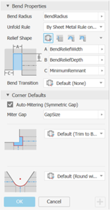
- Define the bend properties, including the relief shape and corner defaults.
- Confirm and finalise the flange.

Was this helpful?
Thanks for your feedback!
