
Reality capture is no longer a futuristic concept. It’s here, it’s powerful, and it’s transforming how we approach renovations, retrofits, factory upgrades, and as-built documentation.
But owning a laser scan and turning it into a usable BIM model are two very different things.
Many professionals ask:
- How do I move from raw scan data to a structured Revit model?
- What happens between ReCap and Revit?
- How do I correctly set up coordinates and levels?
- How do I model accurately from a point cloud?
- And ultimately… how do I produce construction documentation from it?
Step 1: Understanding What You’re Actually Working With


Laser scanners capture millions, sometimes billions, of spatial data points. Each point contains XYZ coordinates and often colour information. Together, they form what we call a point cloud.
Unlike traditional surveying, LiDAR/Faro (or other laser scanners) captures everything visible from the scanner’s position:
- Structural elements
- Equipment
- Pipes
- Floors
- Walls
- Ceilings
- Steel structures
For factory environments or multi-storey buildings, this becomes incredibly powerful, especially when working on upgrades or documentation of older facilities where drawings may be outdated or missing entirely.
But raw scan data is not BIM.
That’s where the workflow begins.
Step 2: Preparing Your Scan Data in ReCap Pro
Before we even open Revit, the scan data needs to be processed and structured inside:
Autodesk ReCap Pro
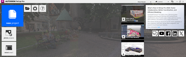


This is where raw scans become usable.
Inside ReCap Pro, you will typically:
- Import raw scan formats (.e57, .las, etc.)
- Register multiple scan positions
- Align scans accurately
- Clean stray or unnecessary data
- Apply clipping regions
- Segment areas (for example, by floor in a multi-storey building)
- Create Groups and Layers to have user-control and visibility control in Revit
- Export a structured project file (.RCP / .RCS)
This step is critical.
If you skip proper preparation here, you will struggle later in Revit, especially with performance and accuracy.
For large factory scans, segmentation can dramatically improve usability. Instead of one massive dataset, you can isolate floors or zones, making modelling far more efficient.
Step 3: Inserting the Point Cloud into Revit
Once the scan is cleaned and indexed, it’s time to move into:
Autodesk Revit

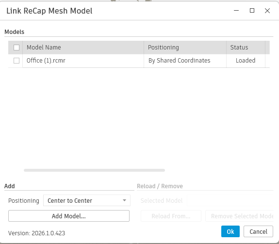

In Revit, the point cloud is linked, not imported. This is important.
You typically choose between:
- Origin to Internal Origin
- By Shared Coordinates
- Center to Center
For construction documentation workflows, understanding positioning and coordinate alignment is absolutely essential.
At this stage, you are not modelling yet. You are setting the foundation.
And this is where many Scan-to-BIM projects go wrong.
The 2 ways to Link a PointCloud file is:
1. Revit Ribbon > Insert Tab > Link Pointcloud
2. ReCap Mesh Extension > Link Recap Mesh Model
Step 4: Coordinates — The Make-or-Break Step


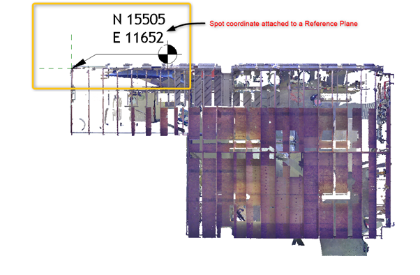
Revit Ribbon > Manage Tab > Project Location Panel > Coordinates and Position – Specify Coordinates.
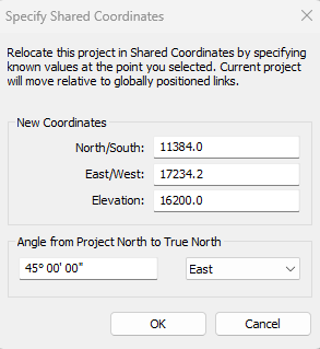
Revit works with two critical reference systems:
- Project Base Point
- Survey Point
If your building is not correctly positioned in real-world coordinates, downstream deliverables can become problematic, especially when collaborating with civil engineers, surveyors, or other consultants.
For factory upgrades, plant expansions, or multi-disciplinary projects, coordinate accuracy ensures:
- Correct site alignment
- Proper north orientation
- Reliable shared coordinates
- Accurate documentation output
This step ensures that your BIM model is not just visually accurate, but geographically correct.
Orientation = Project North / True North
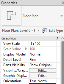
Select a Level Line, either in Elevation or Section View > Properties Palette > Select Edit Type to open the Type Properties > Parameter = Constraints – Elevation base > Select the value to alternate between Survey Point or Project Base Point

Step 5: Setting Up Levels from a Multi-Storey Scan
Once coordinates are established, vertical structure comes next.
In section or elevation views, you can clearly identify slab edges, structural beams, and floor heights within the point cloud.
From there:
- Create levels aligned to scan data
- Validate floor-to-floor heights
- Organize naming conventions
- Confirm vertical accuracy
For multi-storey buildings, this step transforms raw spatial data into an organized BIM framework.
Now you’re ready to model.
Step 6: Modelling from the Point Cloud

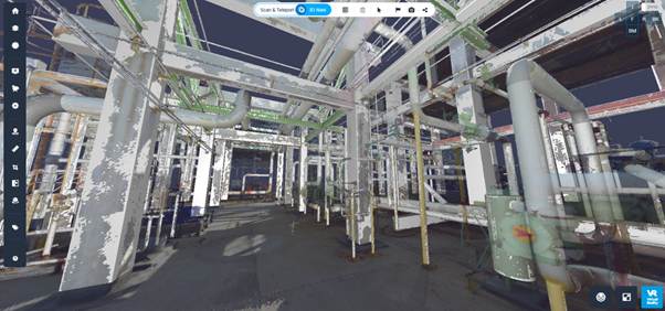

This is where Scan-to-BIM becomes practical.
Using the point cloud as a reference, you model:
Architectural Elements
- Walls
- Floors
- Doors and openings
Structural Elements
- Columns
- Beams
- Steel framing
Industrial Components
- Pipe runs
- Platforms
- Equipment geometry
- Cable trays
But modelling from a scan requires discipline.
You do not model every pipe clamp or every bolt.
Instead, you define a Level of Detail (LOD) strategy:
- LOD 200 for spatial coordination
- LOD 300 for documentation
- Higher LOD for fabrication or retrofit planning
Over-modelling wastes time and reduces performance. The goal is accurate, purposeful modelling aligned with deliverables.
Step 7: Performance & Workflow Optimization
Large point clouds can affect performance.
Best practices include:
- Using section boxes
- Turning off unnecessary scan regions
- Placing point clouds on dedicated worksets
- Splitting scans by building zone
- Avoiding unnecessary duplication
For factory environments especially, file size management becomes part of your BIM strategy.
The cleaner your workflow, the smoother your documentation process.
Step 8: From Scan to Construction Documentation
At this stage, your point cloud is no longer just millions of dots.
It is now:
- A coordinated Revit model
- Structured by levels
- Positioned correctly on site
- Ready for plans, sections, and elevations
- Suitable for renovation drawings
- Prepared for consultant coordination
And that’s the real objective.
Not just modelling from a scan, but producing reliable construction documentation from it.
Understanding the Workflow and Implementation
Scan-to-BIM is particularly valuable for:
- Factory retrofits
- Plant upgrades
- Warehouse expansions
- Renovation projects
- Heritage building documentation
- As-built verification
It reduces guesswork, improves accuracy, and dramatically enhances coordination across disciplines.
But success depends on understanding the entire workflow, not just how to insert a point cloud.
Conclusion
The journey from laser scan to construction documentation is structured, strategic, and highly technical, but when done correctly, it is incredibly powerful.
The workflow can be summarized as:
- Capture reality
- Process in ReCap
- Insert into Revit
- Establish coordinates
- Create levels
- Model with purpose
- Document accurately
When professionals master this pipeline, they unlock a new dimension of BIM, one grounded in real-world data.
And in today’s retrofit-heavy construction industry, that skillset is no longer optional.
It’s essential.
Key Takeaway
Reality Capture and Existing Conditions
Many engineering and architectural projects today involve renovations, retrofits, factory upgrades, or adaptive reuse of existing buildings. In these scenarios, accurate information about current site conditions is critical. Autodesk ReCap Pro, included as part of the AEC Collection, enables professionals to work directly with point clouds generated from laser scanning or photogrammetry workflows.
Because ReCap Pro is integrated within the broader Autodesk ecosystem, it connects seamlessly with tools such as Revit and Autodesk Docs. This means your scan data, BIM models, and project documentation can live within one coordinated digital environment, rather than being scattered across disconnected platforms.
Using ReCap Pro provides:
- Highly accurate existing-condition references
- Reduced reliance on manual site measurements
- Improved alignment between design intent and on-site reality
For building engineers and BIM professionals, this translates to fewer construction surprises, better coordination across disciplines, and greater confidence when making critical design decisions within a unified software collection.
The Autodesk AEC Collection includes all the essential software required to create intelligent 3D BIM models for visual representation, construction documentation, and reality capture. All within one connected ecosystem. With powerful tools such as Revit for BIM authoring, ReCap Pro for processing laser scans and point clouds, and Autodesk Docs for cloud-based collaboration and document management, the AEC Collection provides a complete end-to-end workflow for modern engineering and construction projects.
As an authorized Autodesk reseller, we assist professionals in understanding exactly what is included in the AEC Collection and how these tools integrate to support your specific project requirements. If you would like to learn more about licensing options, implementation strategies, or how to get started with Scan-to-BIM workflows, feel free to contact us, we would be happy to guide you.

