
To facilitate collaboration on an Autodesk AutoCAD Plant 3D project within the Autodesk Forma cloud environment, a minimum software requirement consists of an AutoCAD subscription and a Forma Design Collaboration subscription. Autodesk Forma Design Collaboration provides the Collaboration for AutoCAD Plant 3D entitlement required to host and manage Plant 3D projects in the cloud.
From a project coordination perspective, it is recommended that the project team maintain at least one Autodesk Navisworks Manage subscription. This allows a designated coordinator to aggregate discipline-specific models into a federated model and publish optimized NWC datasets for project-wide review. Team members can then access and navigate the federated model using Autodesk Navisworks Freedom, which is available as a free viewer.
The federated model provides essential design context, allowing Plant 3D users to evaluate their work within the broader multidisciplinary environment, including structural, civil, architectural, and mechanical models.
Navisworks is particularly well suited to this workflow because NWC files are highly optimized for visualization and coordination purposes. Compared to native Plant 3D project files, NWC datasets typically require significantly less memory and graphics resources, enabling large, federated models to be opened, reviewed, and navigated more efficiently on standard engineering workstations. This approach reduces the risk of performance degradation and improves project-wide model accessibility during design coordination activities.
For organisations considering Autodesk Plant 3D cloud collaboration, one of the Autodesk Industry Collections is typically the most cost-effective licensing pathway, as these collections include the required AutoCAD and Autodesk Navisworks software components. Depending on the user’s role, project requirements, and discipline-specific workflows, either the Architecture, Engineering & Construction (AEC) Collection or the Product Design & Manufacturing (PD&M) Collection may represent the most suitable solution.
The Architecture, Engineering & Construction Collection is generally better aligned with multidisciplinary BIM, infrastructure, process plant, and construction coordination workflows, while the Product Design & Manufacturing Collection may be more appropriate where mechanical equipment design and manufacturing processes form a significant part of the project deliverables.
To ensure that the selected software portfolio aligns with both operational requirements and project objectives, we recommend engaging with Micrographics prior to making any investment decision. Our consultants can provide guidance on the most appropriate licensing strategy, cloud collaboration architecture, and workstation hardware specifications required to effectively support Autodesk Plant 3D, Autodesk Forma Design Collaboration, and associated federated model coordination workflows.
Prior to establishing an Autodesk AutoCAD Plant 3D collaboration project on the Autodesk Forma platform using Forma Design Collaboration, an initial Plant 3D project must first be created and configured in a local workspace.
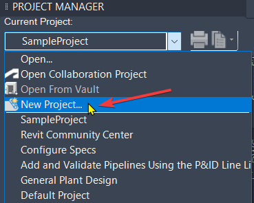
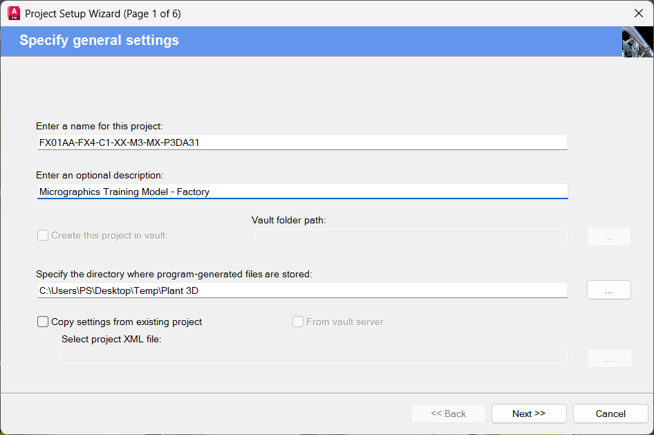
Give the project a name. In this case I’m following my variation on the ISO 19650 naming standard. The description will show up in the details pane of the Project Manager pane.
Now select either the Metric or Imperial unit system.
In Autodesk Plant 3D, the “Inches (Mixed Metric)” project unit configuration represents a hybrid measurement environment in which the model geometry, coordinates, and physical dimensions are stored and calculated in millimetres (metric units), while nominal pipe sizes (NPS), component diameters, and industry-standard piping specification data are defined, referenced, and displayed in inches (imperial units). This configuration supports projects that require metric modelling precision while maintaining compliance with piping standards and specifications that utilize imperial size designations.

Select the P&ID symbology standard that will govern the graphical representation of piping, equipment, instrumentation, and control systems throughout the project.
ISO symbology, typically derived from ISO 10628 and ISO 15519, is widely adopted for projects developed in accordance with international and European engineering standards. For Autodesk Plant 3D projects where no client-mandated standard exists, ISO is generally the preferred option for South African applications, as it aligns closely with the standards commonly specified across the mining, petrochemical, power generation, and water sectors.
DIN symbology may be encountered when working on legacy facilities of German origin or on projects executed in accordance with German engineering practices. However, it is not typically the default standard selected for new South African process plant projects.
JIS and JIS-ISO symbology standards are comparatively uncommon within the South African market and are generally specified only where the asset owner, EPC contractor, or project execution framework requires compliance with Japanese engineering standards.
PIP (Process Industry Practices) standards are also frequently used within the process industries, particularly on projects associated with United States-based owners, EPC contractors, or engineering specifications originating from the petrochemical, oil and gas, and chemical manufacturing sectors. PIP PIC001 provides comprehensive requirements for P&ID documentation, format, and content and is often incorporated into project-specific engineering standards.
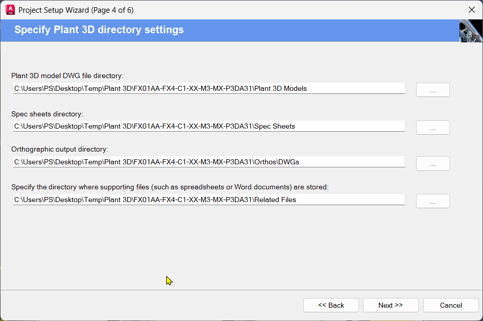
Note the designated directory for P&ID defaults to a sub-directory in the main directory that was chosen earlier.

Note the designated directory for Plant 3D Model DWG, Specs, Orthographic DWG, and Supporting Files all defaults to a sub-directory in the main directory that was chosen earlier. You may also chose another folder if required.
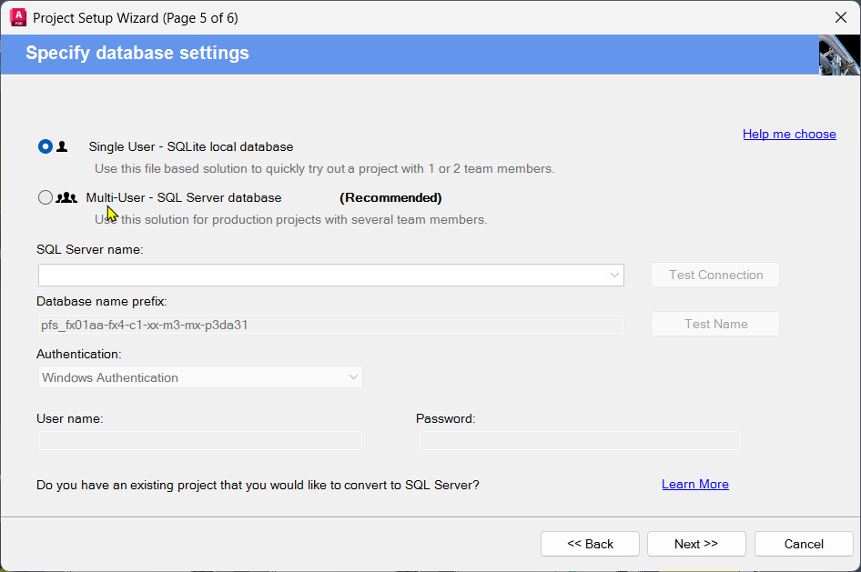
For multi-user project environments operating on a local area network (LAN), Autodesk Plant 3D projects are typically configured to use Microsoft SQL Server as the project database platform, providing centralized data management, concurrent user access, and improved scalability. However, where the project is intended to be migrated to a cloud-based collaboration environment, it is acceptable to initialize the project using the embedded SQLite database, as it provides a simplified deployment model and is adequate for project setup and subsequent cloud publication workflows.
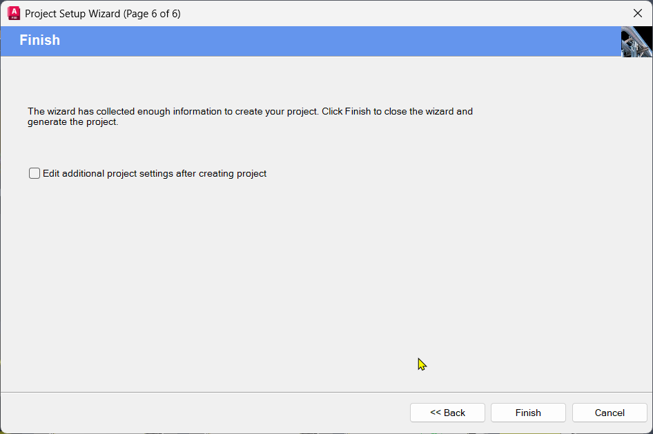
Finish setting up the project.
Create at least one drawing so you can gain access to the Collaborate tab.
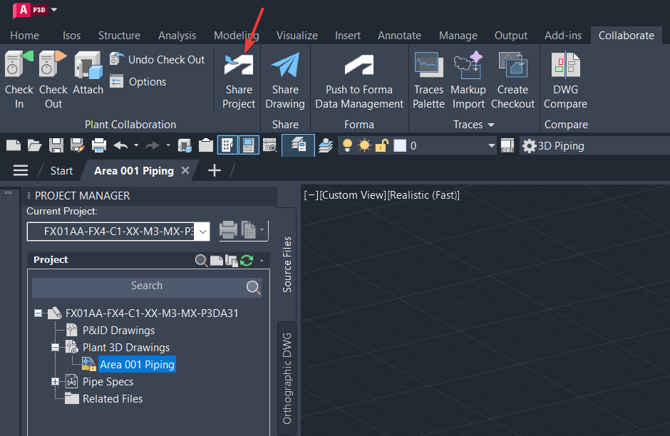
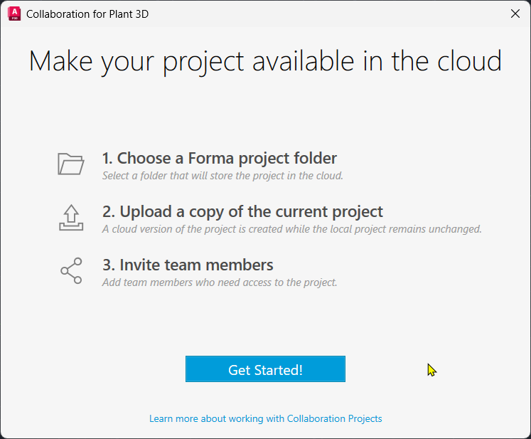
The local project is then published to the cloud environment, where a separate cloud-hosted collaboration project is generated and managed through Autodesk Forma Design Collaboration and Autodesk Forma Data Management (included with your Forma Design Collaboration subscription).
Items 1 and 2 are of relevance to this blog. 3 is managed on the Forma Project by Forma Project Admin, and not within Plant 3D.
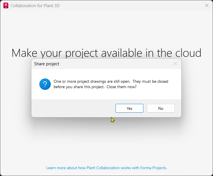
Your open drawing is now closed and the project is uploaded to the Forma Project.
Choose the relevant folder in which you save your project. Note, the below structure is of my own design and that your project folders would probably be more intelligible at first glance. In translation, this folder means the following to me:
b = Work In Progress Folder (Silo)
MX = General Mechanical Task Team
FX4 = Micrographics Team Number 4
A = Project “A” if Bridged into another project
S1 = Site 1
A = Phase A
P3D = Plant 3D Authoring Tool
A3 = PROCSA 4.1 – Local Authority Drawings and Documentation
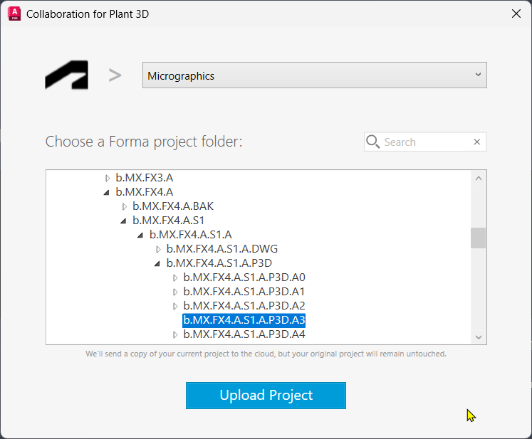
The project is uploaded.
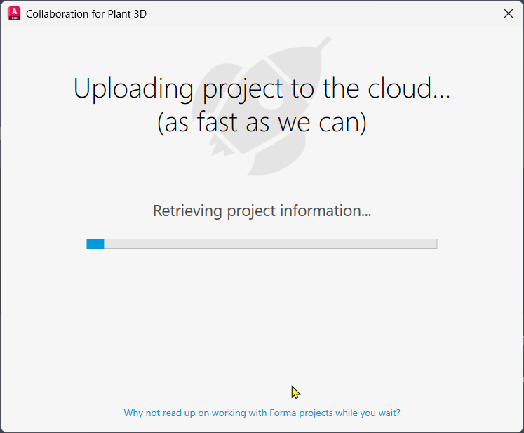
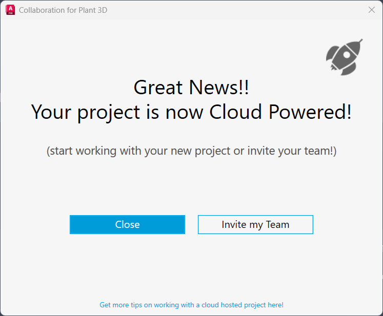
Success!
You can now open the project from the Project Manager dialog.
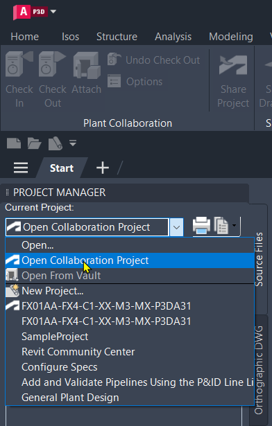
And browse to the project in question.
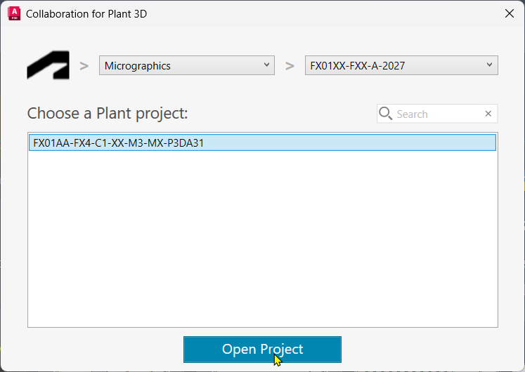
Once a Plant 3D project has been established, a wide range of additional configuration settings become available to support project-specific modelling and documentation requirements. One of the most critical implementation activities is the creation, validation, and ongoing management of piping specifications (Specs).
In Plant 3D, specifications define the allowable piping components that may be used within a given piping class or standard. These specifications control the selection of pipe segments, fittings, valves, flanges, gaskets, and associated component sizes, ensuring that only approved combinations of materials and dimensions can be placed within the model. As such, specs form the foundation of standards compliance and data consistency throughout the project lifecycle.
For users familiar with Autodesk Revit, a Plant 3D specification can be thought of as being conceptually similar to a Pipe Type and its associated Routing Preferences, in that both systems govern the components and connection logic available to designers. However, Plant 3D specifications provide a significantly more comprehensive framework for managing process-industry piping standards, component catalogues, and engineering requirements.
Over the coming months, I intend to explore the creation, customization, and administration of Plant 3D specifications in greater detail. This topic deserves dedicated treatment due to its importance in successful project execution, and I hope to publish additional articles examining specification development, catalogue management, component selection rules, and best practices for standards implementation. As my experience with Plant 3D continues to grow, so too does my understanding of efficient modelling practices and advanced project workflows. The software provides a highly capable environment for process plant design, and I continue to enjoy developing my modelling skills both professionally and through personal study. Fortunately, I have access to experienced Plant 3D specialists who provide valuable mentorship and technical guidance. Their expertise has significantly accelerated my learning curve, and I hope that other users have the opportunity to work within similarly supportive environments where knowledge sharing and collaboration contribute to professional growth and modelling excellence.
If you need help adopting the AEC Collection or Autodesk Forma in your practice or you are looking to invest in hardware, please contact Micrographics so that we may be of assistance.

