One of the most compelling strengths of the Autodesk ecosystem, in my estimation, is the immense integration potential natively engineered into its existing software packages. Within the AEC Collection specifically, there exists a vast array of interoperable workflows; the key lies simply in understanding the methodology of their execution. This capacity for integration ensures that modern workflows are no longer isolated silos, significantly reducing the necessity for redundant remodeling while facilitating seamless transitions across the concept-to-design-to-drawing-to-construction continuum.
One particular process that has consistently impressed me is the Bridge Design workflow, made possible by the synergy of three AEC Collection powerhouses: InfraWorks, Structural Bridge Design, and Revit. When leveraged correctly, this forms a comprehensive, end-to-end pipeline that can be further enhanced through the incorporation of Navisworks. Within this framework, Navisworks serves as a critical tool for both advanced clash detection and 4D Construction Simulations (https://www.autodesk.com/autodesk-university/article/Practical-4D-Construction-Simulation-Using-Revit-and-Navisworks). Let’s delve into the mechanics of this workflow.
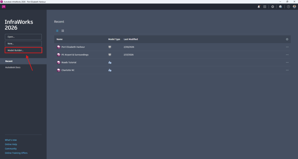
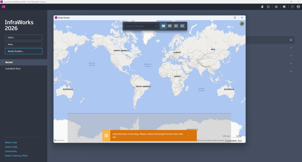
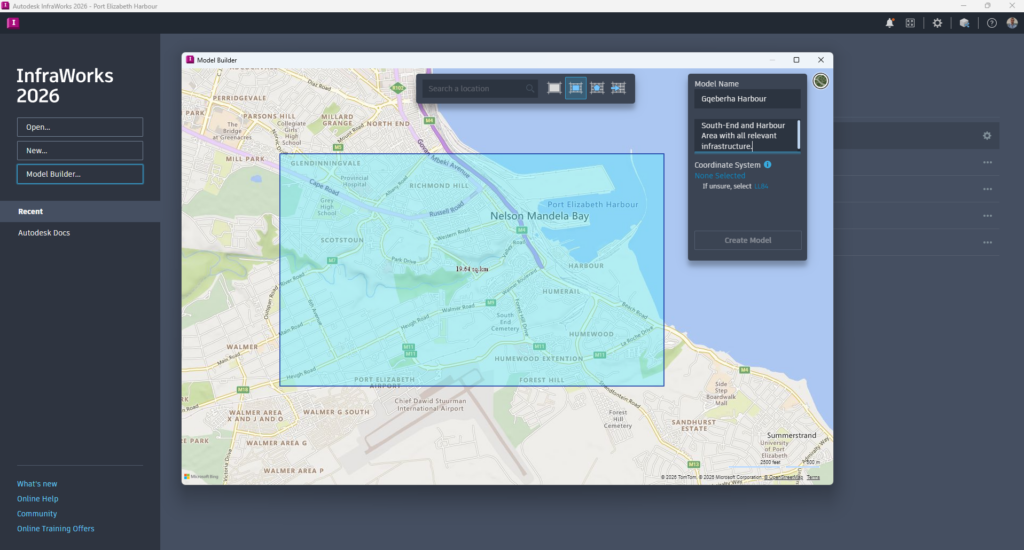
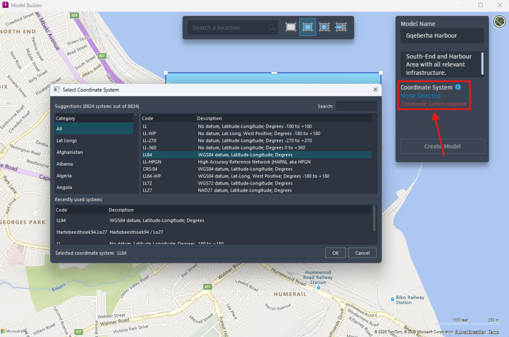
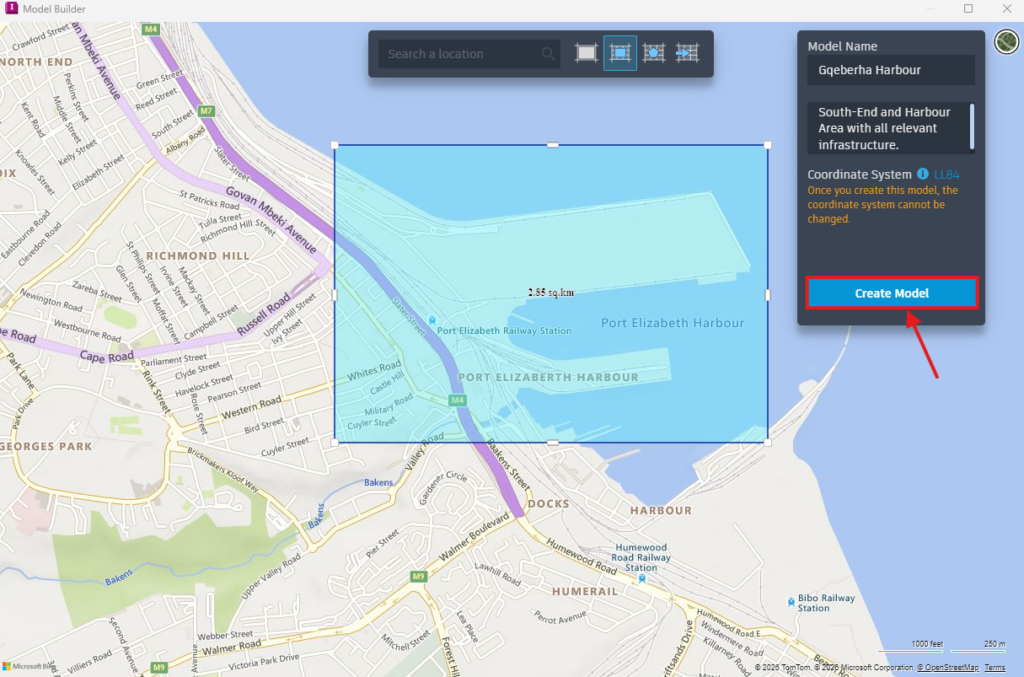
The journey begins in InfraWorks. Upon launching the application, you are presented with the Model Builder tool. Activating this feature opens a global interface, reminiscent of Google Earth, where you can precisely demarcate your project area using the built-in selection tools. This process isolates a specific geographic segment for further engineering utility. In my specific demonstration, I isolated a substantial portion of the South-End area and the harbor in Gqeberha (formerly Port Elizabeth). It is imperative that a Coordinate System is defined before the model generation can proceed. After clicking “Create Model,” a brief waiting period is required while the software aggregates the environmental data.
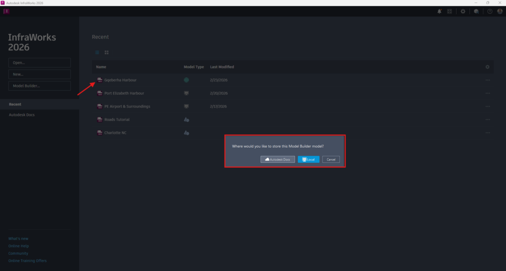
Once generated, the new model will appear on your InfraWorks homepage. Upon opening it, you will be prompted to choose a storage destination: either the cloud via Autodesk Docs or a local directory on your machine.
With the model successfully saved and loaded, you can navigate the 3D environment to identify the specific infrastructure slated for development. Our primary objective is the creation of a bridge for subsequent export to Revit. It is important to note that, initially, the model will not contain “intelligent” bridge objects. While you may see structures that visually resemble bridges, selecting them will reveal they are categorized merely as standard road assemblies. To progress, you must manually define the bridge structure.
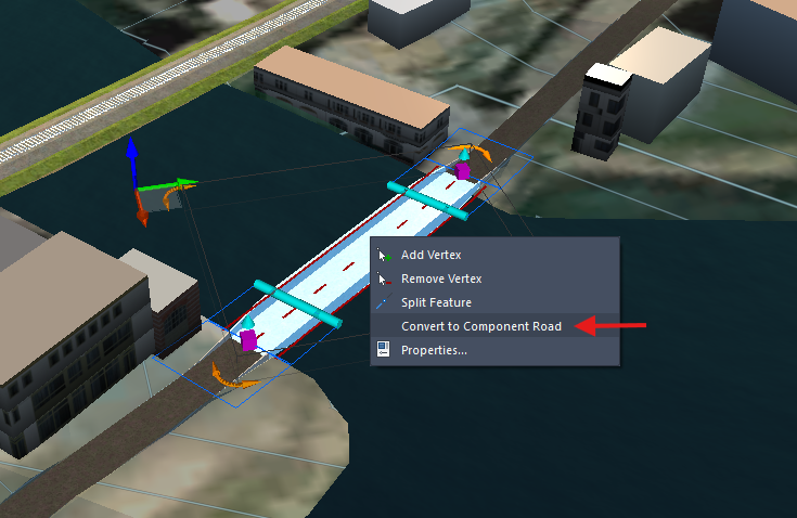
The preliminary step involves converting a specific segment of the existing road into a Component Road. To achieve this, select the desired road section, right-click, and choose the “Convert to Component Road” option from the context menu.
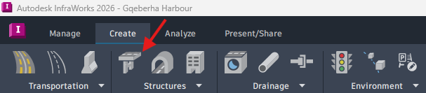
Now, you are ready to generate the bridge. Navigate to the Create tab in the InfraWorks ribbon and select the Bridge button located within the Structures panel. Upon activation, a contextual prompt will appear at the bottom-center of your workspace to guide you through the process, highlighting eligible Component Roads.
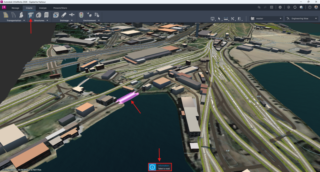
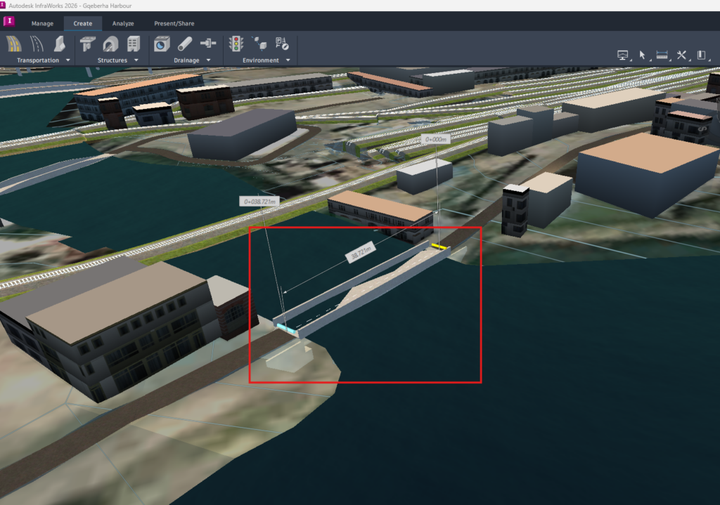
With the road selected, you must define the bridge’s longitudinal extents. This is done by positioning your cursor and left-clicking to set the start and end stations. The software will then procedurally generate the bridge structure.
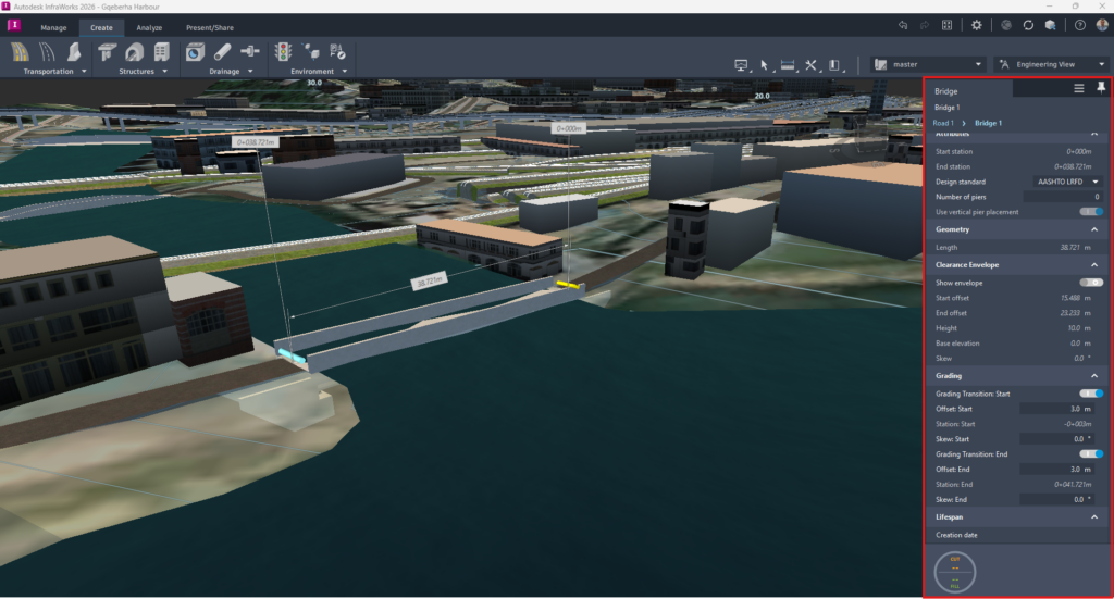
To accurately select the bridge itself—rather than the parent road—it is often easiest to rotate the model to a sub-surface view, looking at the structure from below, and then selecting one of the abutments. This action populates the Properties Panel on the right-hand side with detailed bridge metadata. From here, you can select individual components to modify specific parameters for girders, piers, and abutments. Once the design meets your requirements, you are ready for export. Right-click the bridge and select the Publish Civil Structures option.
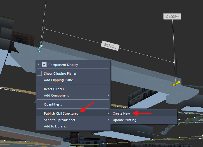
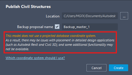
At this stage, you must specify the export destination and, crucially, verify the coordinate system. The default Latitude/Longitude (LL) system is generally insufficient for precise BIM coordination. By clicking the “Create” button, you can navigate to the bridge’s Model Properties to refine these settings. Clicking the globe icon adjacent to the UCS information allows you to browse and select a coordinate system appropriate for your local region.
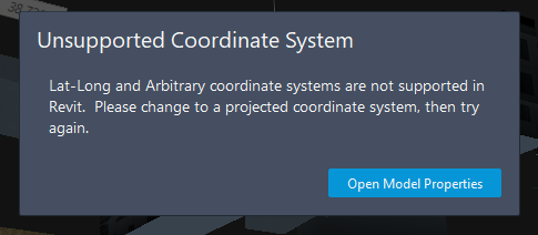
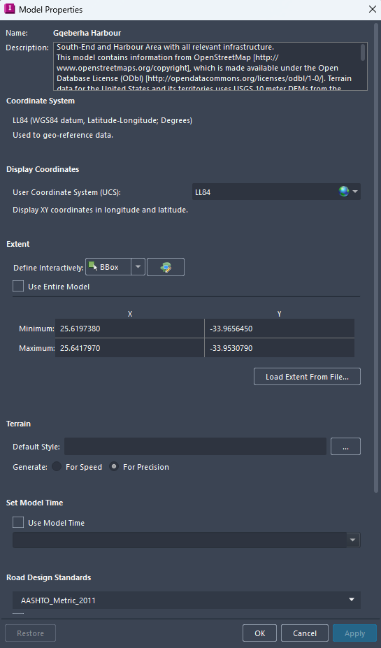
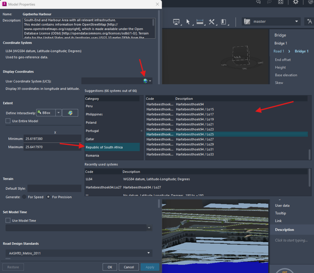
Once these parameters are applied, repeat the Publish Civil Structures command. A successful publication will result in a .imx file. With this file generated, you can close InfraWorks and transition to the next phase.
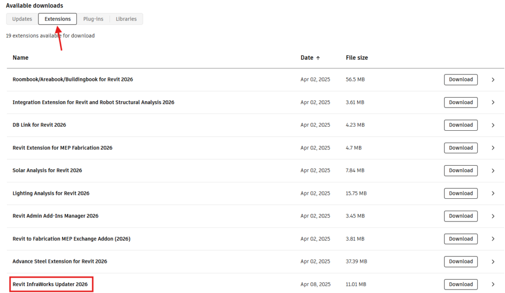
Before proceeding in Revit, ensure that the Revit InfraWorks Updater is installed on your system.
With the update active, launch Revit and navigate to the Add-Ins tab, where you will find the Import Civil Structures tool. Note that upon your first attempt to use this tool, a dialog box may appear stating: “A Shared Parameters File Must be Set in Order to Import Civil Structures.” To resolve this configuration requirement, please refer to the following instructional video:
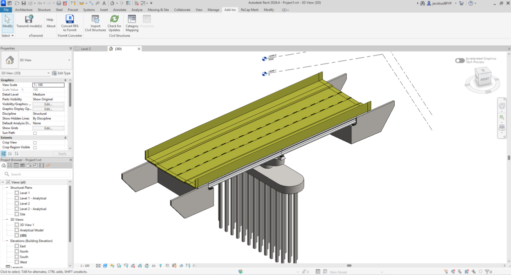
Once the shared parameters are correctly configured, return to the Add-Ins tab, execute the Import Civil Structures command, and select your .imx file. From this point forward, the bridge exists as a native-like object within the Revit environment, allowing you to modify geometry, add intricate details, host reinforcement (rebar), and generate construction documentation as per your standard professional workflow.