
Adaptive design in Autodesk Inventor allows components and features within an assembly to automatically adjust their size, position, or geometry based on changes in related parts. This functionality enables designers and engineers to create flexible, parametric models that update dynamically as design modifications occur.
By using adaptive features, users can establish relationships between parts, ensuring that components remain properly aligned and functionally connected throughout the design process. Adaptive design is particularly useful during the conceptual and early development stages, where dimensions and configurations frequently change.

General steps on how to utilise adaptive design.
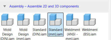
Create a New Assembly (IAM)
Start by launching Autodesk Inventor and creating a new assembly file (IAM). This will serve as your top-level model to host all components.
Initiate Component Creation
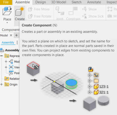
In the assembly environment, navigate to the Assembly tab. Within the Component panel, click on “Create.” This will open a dialogue box where you can define your new component.
Define Component Parameters
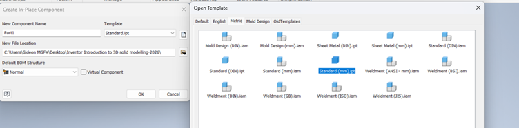
In the component creation dialogue,
Name Your Component and Template
After opening the component dialogue, assign a name to your component. Choose an appropriate IPT template that aligns with your design needs. You can also specify the file location and how it should be organised within the assembly structure.
Set Virtual Component and Type
Decide if your component should be virtual. A virtual component doesn’t exist as a separate file but stays within the assembly. This is useful for reference parts or placeholders.
Confirm the Plane Selection
Once your component is created, choose a plane where you will place it. This could be the front, top, or side plane, or you could select a specific origin point depending on your design intent.
Creating your base component
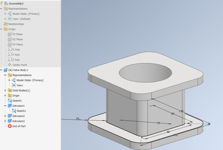
After you have created your base components within the assembly, open the 3D Model workspace. This environment allows you to create and refine the detailed geometry of your first base part. Once you are inside, you can add sketches, features, and further constraints as needed for your part design.
Return to the Main Assembly
Once you have finished designing your base component, return to the main assembly. You can do this by either clicking back into the assembly environment or double-clicking on the assembly from the browser. This will ensure that all updates from your new component are reflected in the overall assembly.
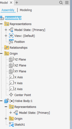
Place Subsequent Components
Repeat the process for any additional components. For each new part, define the plane where it will be constrained to a previous component. This creates a dependency between parts.
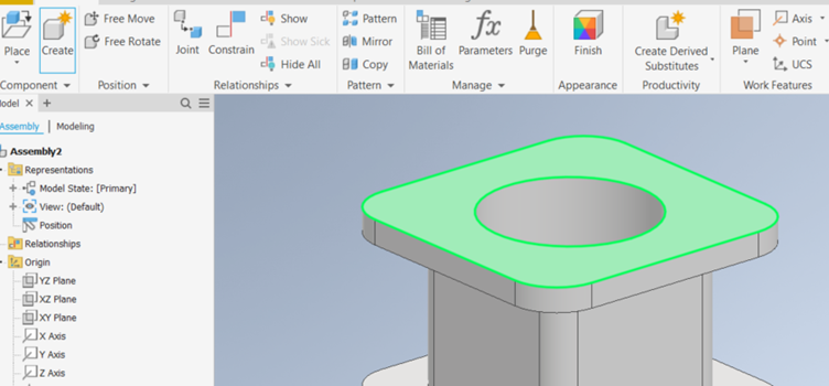
Create a Sketch with Projected Geometry
After positioning each component, create a new sketch on that plane or face. Use the “Project Geometry” tool to bring in edges or features from the previous part. This ensures that your new component’s geometry is tied to the original.
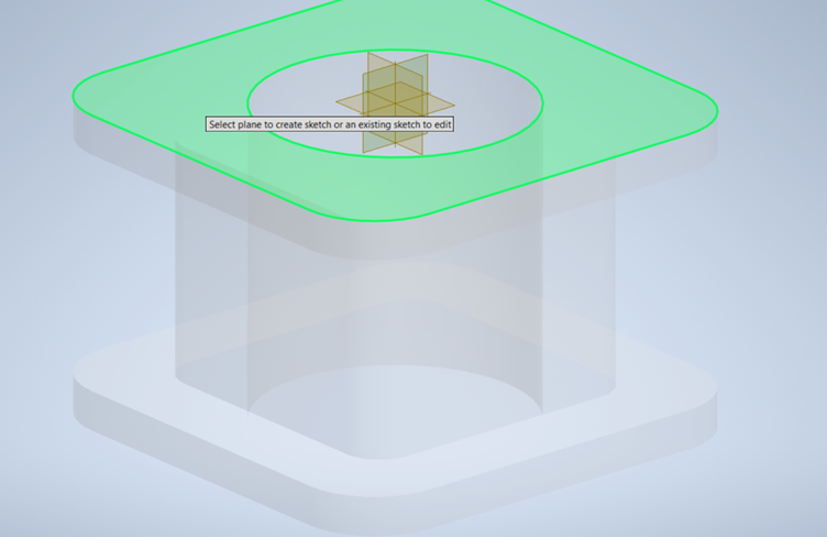
Establish Adaptivity
By linking your sketch to the projected geometry, the new component will become adaptive. If the original geometry changes, these updates will propagate automatically to the dependent components.
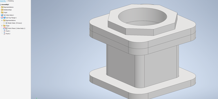
Verify in the Model Browser
Check the model browser for the adaptive symbol next to your components. This visual cue confirms that the component is linked and will update when the source part changes.
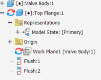
Key benefits of using adaptivity
- Efficient Design Changes: Once a source part is modified, all dependent components update automatically, saving time and reducing manual rework.
- Top-Down Design Flexibility: Adaptivity allows you to drive component sizes and placements directly from the top-level assembly, ensuring alignment and coordination.
- Improved BOM Accuracy: Because components adapt to the primary part, your Bill of Materials (BOM) stays accurate, reflecting the real-time geometry and structure.
- Reduced Redundancy: Instead of creating separate sketches for each part, adaptivity lets you reuse geometry, cutting down on redundancy.
- Better Collaboration: Changes made by one designer at the top-level cascade through the assembly, keeping the entire team aligned with the latest design.
These benefits really help streamline the workflow and keep everything in sync!
A few practical examples:
First, in a modular product design, like a configurable enclosure, you can adjust the size of a mounting bracket based on the main chassis dimensions. As the chassis grows or shrinks, the bracket automatically scales to fit.
Second, in a mechanical assembly, like a gearbox, if you alter the shaft length or diameter in the top-level design, all associated gears and housings adjust accordingly, ensuring proper fit and alignment.
Third, in a custom furniture design, imagine a shelving unit—if the overall height or width of the unit changes, all shelf components resize automatically to match, ensuring a perfect fit each time.
These examples show how adaptivity keeps designs flexible, reduces rework, and ensures all parts stay in sync with your overall model.
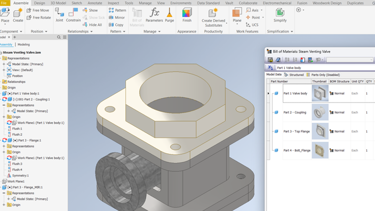
After you’ve finished defining and creating your adaptive parts, you can revisit each individual component by either double-clicking it directly in the model browser or right-clicking on the part and selecting “Open.”
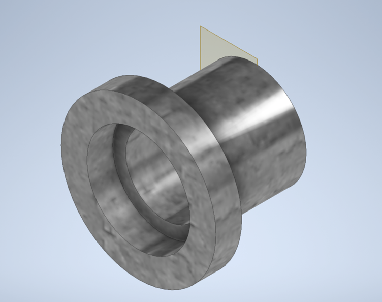
Once inside the individual part file, you have a full suite of tools to define its iProperties. These can include crucial details like material specifications, project names, part numbers, stock-keeping units (SKUs), and other metadata that are essential for downstream processes. By meticulously filling out these attributes, you create a structured, searchable, and well-documented part library.
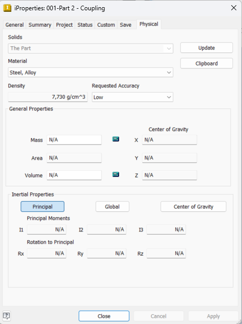
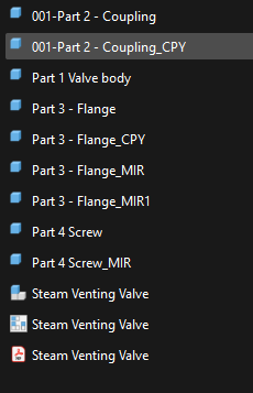
Once all changes are complete, you save the entire assembly. At this moment, each part file is automatically saved individually in its designated folder location. This means that every part is now a separate, standalone file, organised exactly where you intended. This structure not only keeps your project tidy but also ensures that each part is ready for further use—whether that’s for manufacturing, procurement, or collaboration across teams.
Even when you open each part individually, the adaptive connections remain intact and clearly visible. You can see the reference geometry, and any constraints or projected features tied to the top-level assembly still exist. As a result, if you make a change to the original assembly geometry—like adjusting a key dimension—those changes will still propagate back to the parts. This gives you full confidence that every component stays synchronised, no matter how deeply you examine them, ensuring a robust, flexible design process


