
We would like the door in Revit to have an offset from the floor as well as from the top jamb, so first define a reference plane in the interior elevation view and assign a base offset parameter to it.
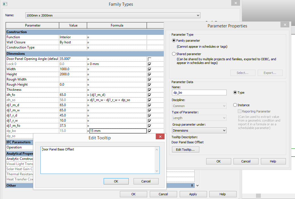

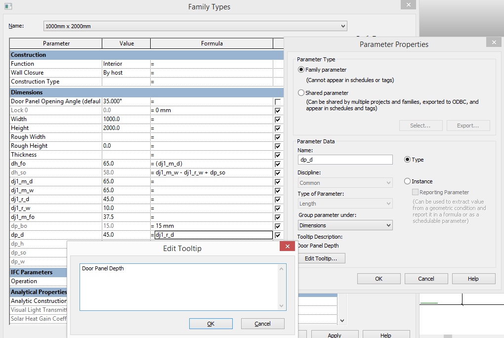
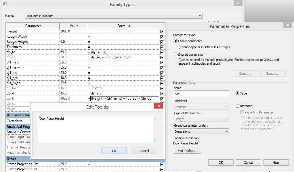
We also define parameters for the door panel depth, height and width in Revit.
(dp_d) = (dj1_r_d)
(dp_h) = (Height) – (dj1_m_w) + (dp_so) – (dp_bo)
(dp_w) = (Width) – 2 * (dh_so)
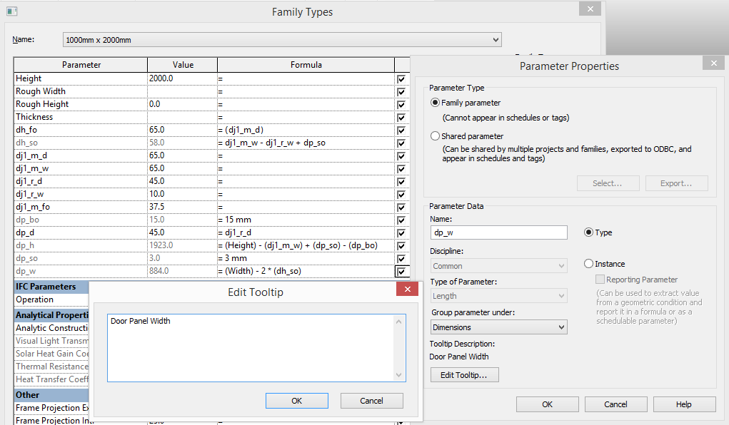
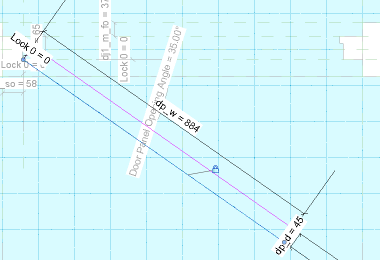
In the Ref. Level Floor Plan, set the workplane to Door Panel Base. Create the door panel extrusion with the profile locked to the hinge reference line. Assign the zero length parameter to the distance from the door panel to the hinge, the relevant parameters to the door panel width and depth as well.
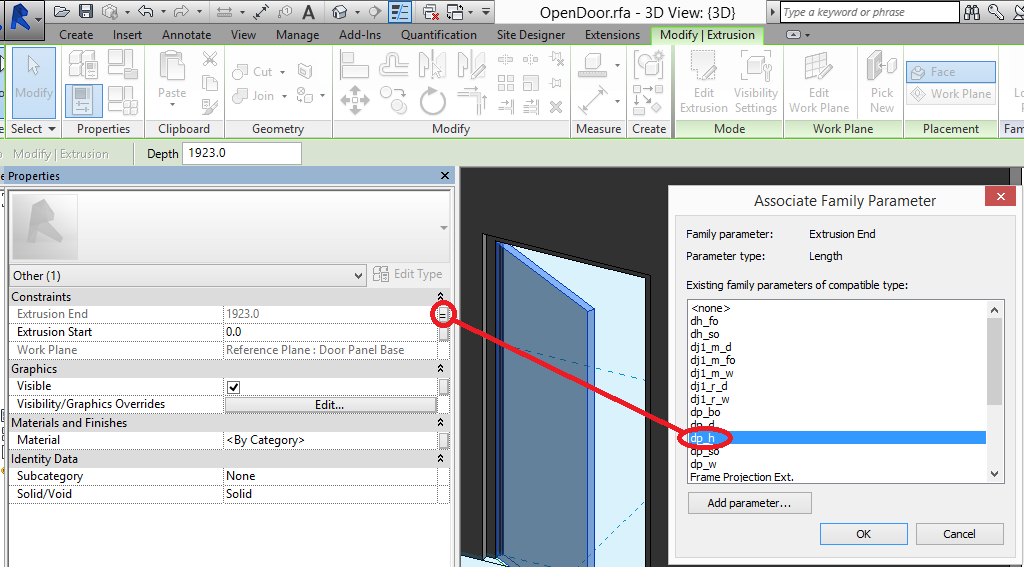
Make sure the extrusion has the correct height by associating the parameter from the properties panel of the door panel.
Flex the door to make sure it works. Note that this door works as long as the opening angle is between 0° and 90°, otherwise it flips to the wrong side of the reference line. Save the Family.
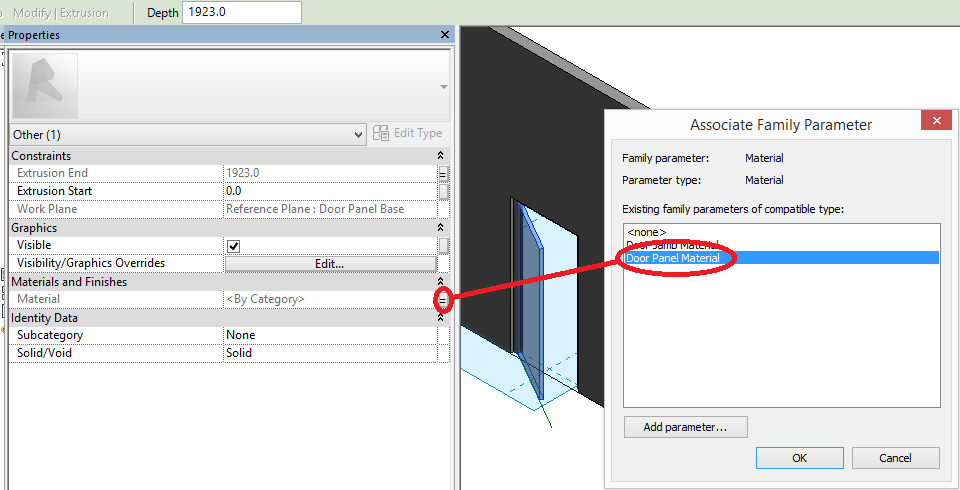
Define and assign material parameters to the door components (Door Jam and Door Panel).

Sweep architrave profiles on the outer and inner edges of the door opening. Similar to the Door Jamb, the architrave profile may also be defined in family file, but we are sketching them inside the door family this time. Work in the Interior elevation.
Set the workplane to the Inerior workplane and pick the edges of the door opening for the sweep.
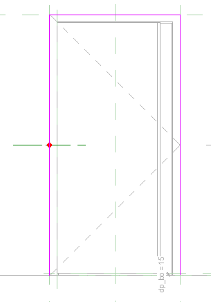
Edit the profile and view it from a plan view. Sketch it as required and then complete the sweep.
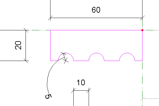
Flex the family to make sure the architrave adjusts to the door size.

Repeat the process for the exterior architrave, this time usign the exterior reference plane as the workplane and the exterior elevation view to pick the path from.

Create a material parameter for the architrave and associate the material properties of the architraves with it.

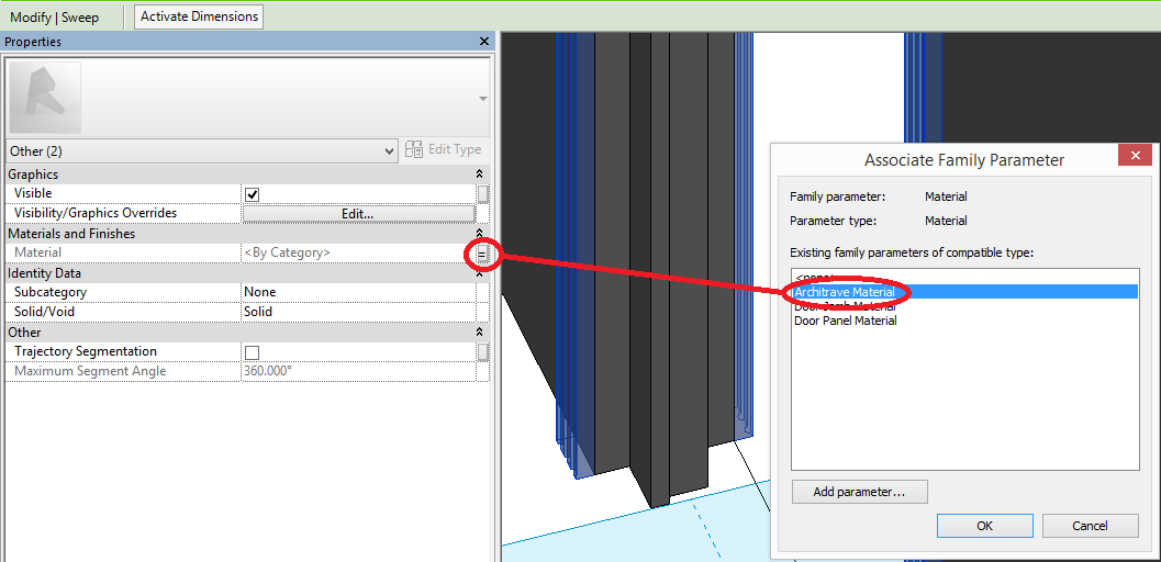
Now set the door components to correspond to the correct subcategories for the door family. This allows the users of the door family to override the visibility graphics of the subcategories when it is loaded into a project.
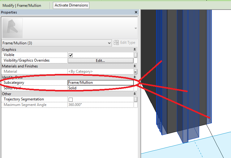

Set a default material for the material properties. If use render appearance is selected then the wooden color will show up in shaded view. Note a custom material can be created for the door components as well.

Now, when viewed in realistic view style the wooden material is evident.
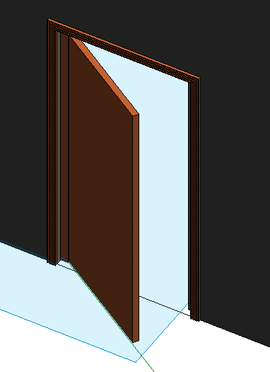
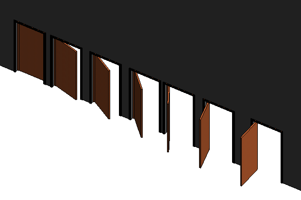
Save the family, import it into a project and host it in a wall. Select the door and note the door has a door opening angle available as an instance parameter. It works for angles between 0° and 90°. Set it for each door instance as required.

All these doors are of the same type with their door opening angles set at 15° intervals between 0° and 90°.
Clearly a frame inside the door cavity could have been created, but it was felt that, for concept illustration, it would be omitted. When creating your own opening door family, include as many components as needed, but be careful to be consistent in parameter creation and usage in formulae.
In the next blog we’ll investigate how to redefine the hinge to accommodate an imported door panel (where an extrusion profile is not associated with the hinge reference line).
